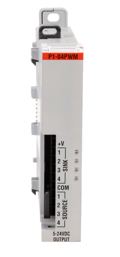
This module can be used to generate up to four PWM signals for use in control applications.
float dutyCycle = 50.15; // Set duty cycle to 50.15%
				int frequency = 10000;	// Set frequency to 10kHz
				P1.writePWM(dutyCycle, frequency, 1, 2); // Set duty cycle and frequency of slot 1 channel 2
Configuration Tool
Compatible Functions
- ch.duty_cycle
- ch.frequency
- ch.value
- module.missing24
- module.values
Properties and Methods
Module Data
We recommend using the status functions and configuration tool. These tables are provided as additional reference.
Module Status Data
| Bytes | (MSB) 7 | 6 | 5 | 4 | 3 | 2 | 1 | 0 (LSB) | Description |
|---|---|---|---|---|---|---|---|---|---|
| Byte 0 | x | x | x | x | x | x | x | x | bits 0-7 are undefined |
| Byte 1 | x | x | x | x | x | x | x | x | bits 0-7 are undefined |
| Byte 2 | x | x | x | x | x | x | x | x | bits 0-7 are undefined |
| Byte 3 | x | x | x | x | x | x | x | 0 | bits 1-7 are undefined |
| bit 0 - Module diagnostics failure |
Module Configuration Data
Default values are in bold.
| Bytes | (MSB) 7 | 6 | 5 | 4 | 3 | 2 | 1 | 0 (LSB) | Description |
|---|---|---|---|---|---|---|---|---|---|
| Byte 0 | x | x | x | x | x | Mode | 1 | 0 | Channel 1 |
| Bit 0 - Must be "0" | |||||||||
| Bit 1 - Must be "1" | |||||||||
| Bit 2 - Mode: 0 = PWM, 1 = DIR |
|||||||||
| Byte 1 | x | x | x | x | x | Mode | 1 | 0 | Channel 2 |
| Byte 2 | x | x | x | x | x | Mode | 1 | 0 | Channel 3 |
| Byte 3 | x | x | x | x | x | Mode | 1 | 0 | Channel 4 |
Note: Bits 0 and 1 must be set to "0" and "1" respectively for each config byte on the P1-04PWM.

Channels: 4
Output Type: Open Drain Sinking or Sourcing
Rated Voltage: 5-24V
Frequency: 0-20kHz
Examples:
Arduino
CircuitPython
Additional Resources:
Data Sheet
P1-04PWM
on AutomationDirect.com