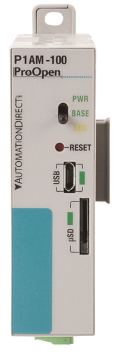
The ProductivityOpen P1AM-100 is an automation platform compatible with Productivity1000 Series I/O modules, P1AM Series shields, and Arduino MKR format shields. It can be programmed using the Arduino IDE. The board uses the SAMD21G18 Microcontroller like the Arduino MKRZERO and other similar boards.
Productivity1000 Series modules offer several types of industrial grade I/O:
Analog and Temperature Inputs
Analog Outputs
Discrete Inputs
Discrete Outputs and Relays
Specialty Modules
Compatible Functions
Below are several functions that are used to communicate with the Base Controller. Look through the examples included in the P1AM library and the source code to get a better understanding of these functions. If you're looking for functions to interface with modules, please check out the page for your module in the sidebar.
Base Controller
The P1AM-100 and accompanying library provide a connection to the Base Controller circuitry. This allows for communication with Productivity1000 Series I/O modules. You are required to provide external 24V or use a P1000 Series power supply when using the Base Controller.
Base Controller Pins
The P1AM-100 uses SPI to communicate with the Base Controller. Because of this, it is possible that pins 8, 9 and 10 can be shared with other SPI devices. However, A3 and A4 cannot be used for any other device while using Productivity modules.
| Pin | Function |
|---|---|
| 8 | MOSI |
| 9 | CLK |
| 10 | MISO |
| A3 | CS |
| A4 | ACK |
Base Controller Watchdog
The Base Controller has a configurable watchdog that can be used to reset the SAMD21 and/or the P1000 Modules in the base. If the Base Controller does not receive a message from the SAMD21 in the configured time period, the watchdog will trigger and take action. This can be useful for if your program encounters an unexpected condition. Check out the watchdog examples for more information on how to use this feature.
CPU Features and Indicators
Toggle Switch
The toggle switch can be used like a normal digital input. It doesn't alter any behaviour on its own so make sure to write code to include any desired functionality. It can be referenced using 31 or SWITCH_BUILTIN. Set it as an input using pinMode() and read it using digitalRead().
pinMode(SWITCH_BUILTIN,INPUT);	//Set Swtich to be a digital input
				Serial.println(digitalRead(SWITCH_BUILTIN);	//Read and print out state of switch. 1 is up and 0 is down.
microSD Card
The microSD card slot can be used to read and write files. This can be useful for logging errors and storing any readings. The CS pin is 28 or SDCARD_SS_PIN. Use the examples in the Arduino IDE to learn how to use this feature.
PWR LED
When this LED is on it indicates the SAMD21G18 is powered on via: USB, external 24V, VIN pin on the header, or a P1000 Series power supply.
Base LED
When this LED is on it indicates the Base Controller is powered and has been intialised by calling P1.init().
Note: External 24V or a P1000 Series power supply must be used for the Base Controller and modules to be powered.
Yellow LED
This LED is a user controlled LED like those found on Arduino boards. It can be referenced by using LED_BUILTIN or 32. It can be controlled with the digitalWrite() function.
pinMode(LED_BUILTIN, OUTPUT);      //Set LED to be a digital output
	digitalWrite(LED_BUILTIN, HIGH);   // Turn the LED on
	delay(1000);                       // Wait 1 second
	digitalWrite(LED_BUILTIN, LOW);    // Turn the LED off
	delay(1000);                       // Wait 1 second
RTC
The P1AM-100 contains an internal RTC (real-time clock) powered by a 32.768 kHz Crystal. An RTC is a clock that keeps track of the current time and can be used to program actions at a certain time. To use the RTC feature download the RTCZero library from the Arduino Library Manager and check out their examples. For more in depth information, see their API reference.
Reset Button
Tapping the reset button once can be used to manually reset code execution, the Base Controller, and all P1000 Series modules.
Quickly double tapping the reset button will put the board into bootloader mode. This mode is indicated by a "breathing"
pattern on the yellow LED. This mode can be used to recover a board that has reached a hard fault due to bad code. Once
in this state, the COM port will change so it is required that you select the new COM port from the tools menu and re-upload your code.
MKR Expansion Header Pins
| Function | Pins |
| GPIO | A0-A6, 0-14 |
| Analog Input | A0-A6 |
| Analog Output | A0 |
| PWM | 0-8, 10, A3, A4 |
| Interrupt | 0, 1, 4-8, A1, A2 |
| SPI | 8, 9, 10 |
| I2C | 11, 12 |
| UART | 13, 14 |
| 5V | 5V supply output |
| Vin | 5V regulated supply input |
| VCC | 3.3 V supply output |
| GND | Ground |
| RST | Reset |
| Aref | Analog Input Reference |
Do not exceed 46mA combined from pins 0, 1, and 4–10.
Do not exceed 3.3 V on any I/O pin.
Do not exceed 7mA on any I/O pin.
Do not apply power to 5V or VCC
Powering the P1AM-100
System Supplies
The P1AM-100 can be powered several different ways. When an external 24V or a P1000 Series supply is connected and turned on the power from USB and VIN is disconnected, but the data lines are still available for programming and monitoring as normal. Additionally, if only VIN and USB are connected, the power from USB is disconnected. WARNING: DO NOT CONNECT EXTERNAL 24V AND A P1000 SERIES POWER SUPPLY AT THE SAME TIME
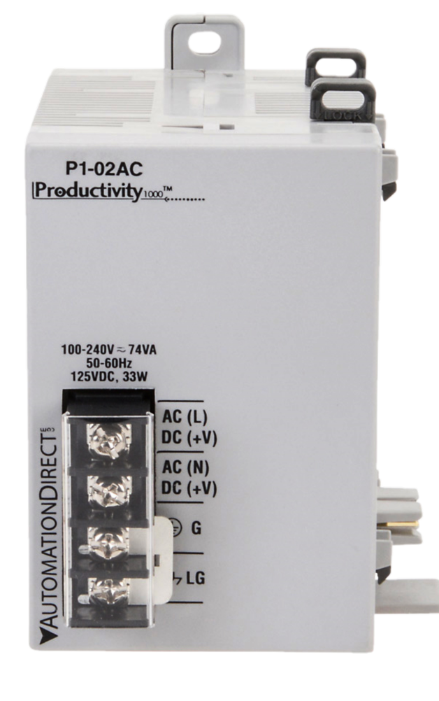
P1000 Series Power Supplies offer noise filtering, electrical isolation, and an easy connection for P1AM systems. There are both AC and DC
input power models.
Power Supplies can be purchased here.
It is important to evaluate your system and determine the amount of power it will need. If you are using any Productivity1000 Series modules, you should budget 1.25W for each slot from your external 24V or P1000 Series supply. If you are using any shields or devices connected to the MKR header, you should refer to the table below to make sure you are within the proper specification. Depending on the power source used, the VCC(3.3V) pin and 5V pin will have different current limits. Additionally, they have a combined total power limit.
| Source | P1000 Modules | P1AM Shields | MKR Shields |
|---|---|---|---|
| USB | X | ✔ | ✔ |
| VIN | X | ✔ | ✔ |
| P1000 Series Supply | ✔ | ✔ | X |
| External 24V | ✔ | ✔ | ✔ |
| Power Source | 5V | 3.3V | Max Combined Power |
|---|---|---|---|
| USB | 330mA | 500mA | 1.65W |
| VIN (Pin Header) | 600mA | 1A | 3.3W |
| P1000 Series Supply OR external24V |
850mA | 1.28A | 4.25W |
Microcontroller: SAMD21G18
Clock: 48MHz
Flash: 256KB
Ram: 32KB
Storage: microSD
RTC: 32.768 kHz Crystal
P1000 I/O Modules: Up to 15. Requires external 24V or P1000 power supply.
Additional Resources:
Data Sheet
P1AM-100
on AutomationDirect.com